Making a Eurorack module
2018-02-18
I’ve spent the last twelve months getting into analog modular synthesizers and building my own Eurorack system.
One thing that almost every modular synth needs is a way to reduce the final output signal to a level that headphones or computer audio interfaces accept.
That level is called “line level” and it usually should be between -1.5 and + 1.5V, preferably even less to avoid clipping. Audio signals in a Eurorack modular synth however often range from -5 to +5V so they need to be
lowered before sending them to any other audio gear. This signal processing is called “attenuation”.
In my system, I often need one to three outputs and I’ve been using my two dual VCAs for that most of the time.
The problem with that is those VCAs could be much more useful for other things so I wanted to have a dedicated output attenuator with four channels.
An attenuator is probably the simplest synthesizer module there is so it’s probably a good starting point to try building your own modules and Doepfer even have a schematic for it right on their DIY website.
So, I went to my trusted local electronics hobby store and picked up the parts and had myself a nice weekend project that I’d like to share.
The parts are:
- 1 Doepfer A-100 blank module plate, 8HP wide
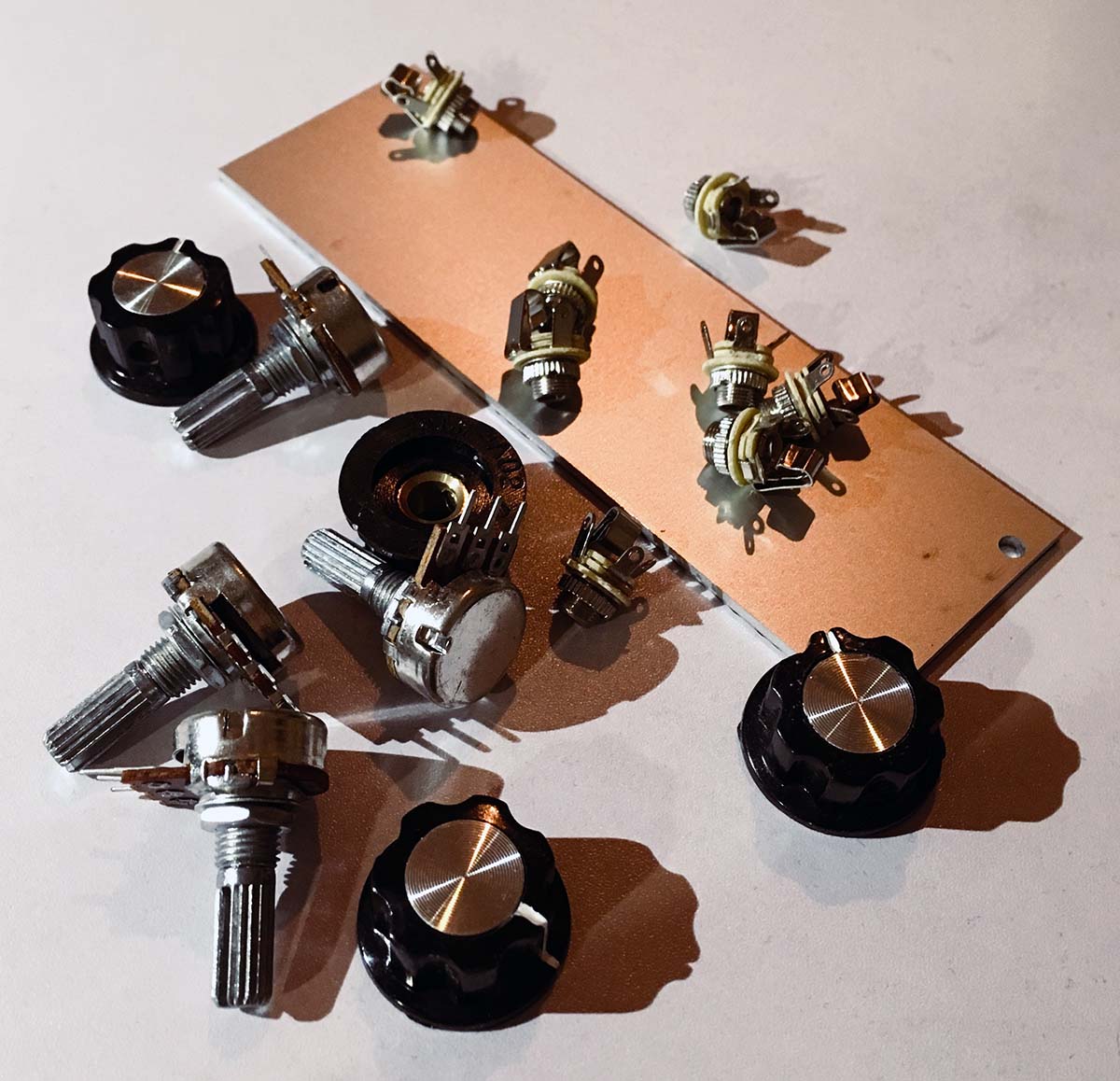
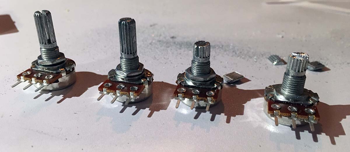
- 4 logarithmic potentiometers, 100kΩ
- 4 turning knobs
- 8 3.5mm TS (mono) jacks
- some red and black wire
I strongly recommend using a professionally made module plate so that the screw holes are in exactly the right place.
Drilling them even half a millimeter off could mess up an entire row of modules. The potentiometers are logarithmic because the loudness of audio signals is perceived more closely to a logarithmic scale than a linear one.
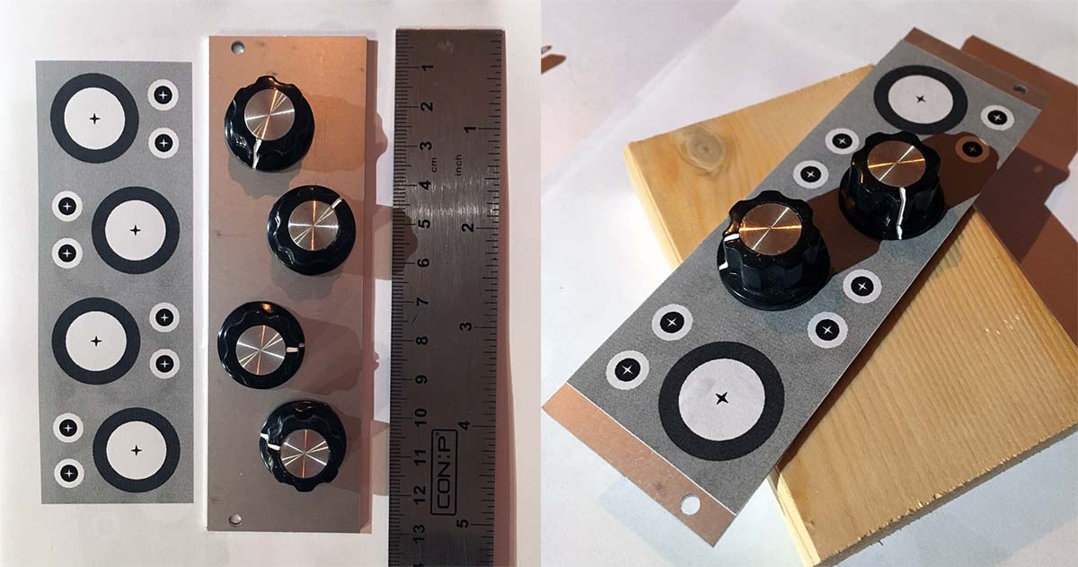
First I laid out the design of the module in a vector graphic program, I used Sketch for the design and Photoshop for a precise print, but anything that can produce an exact print will do. The measurements where taken from Doepfer’s mechanical specs page.
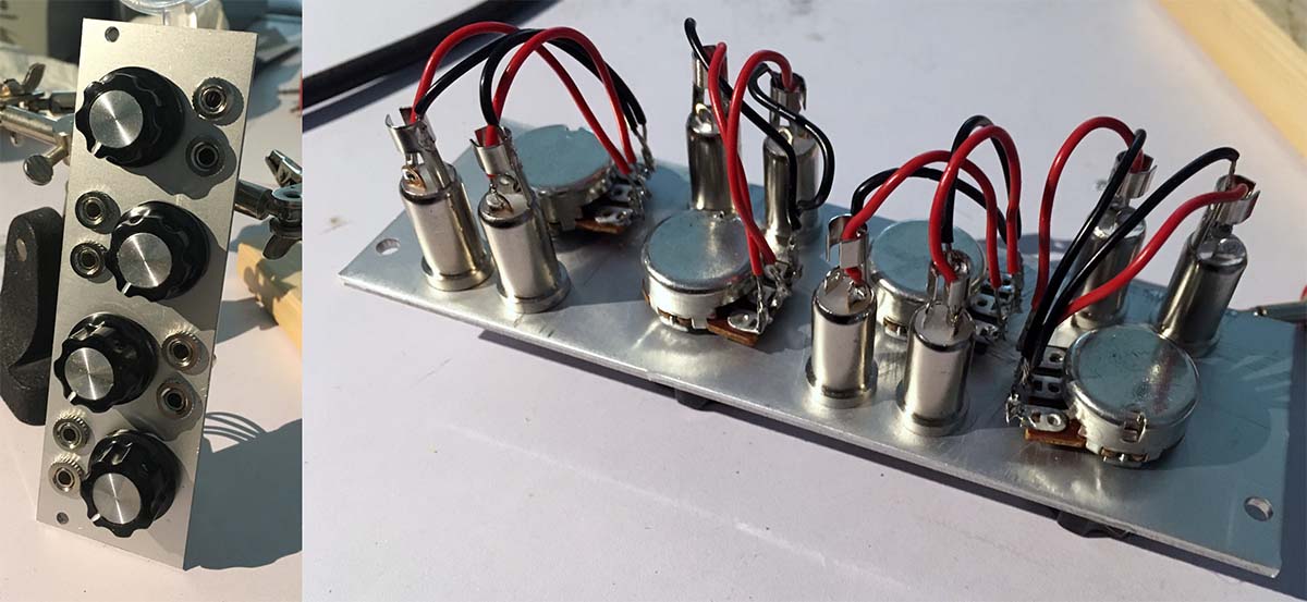
The module consists of four identical circuits, each having an input jack, a potentiometer and an output jack.
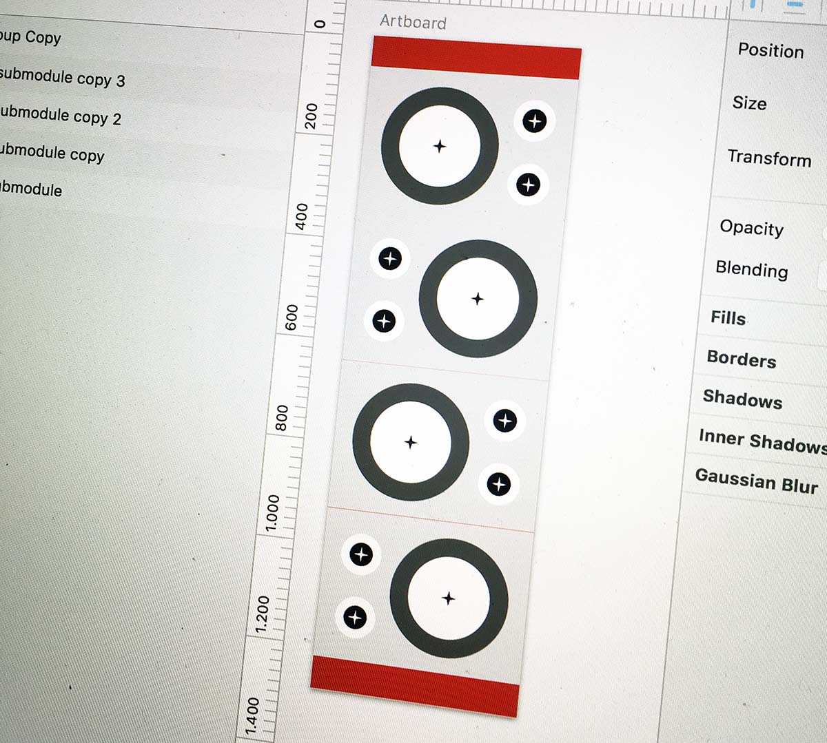
After printing and cutting out the design, I glued the paper to the front of the module plate and checked once again that everything fits nicely.
For the holes in the plate I started by punching a small dent into the metal with a hammer and nail at each center of a hole. After that I used 2, 4, 6 and 8mm drills to make increasingly larger holes.
WARNING: The aluminum of the front plate is very soft and the drills sometimes tend to “grab” the material and spin the plate around. Since the plate has slightly sharp edges this can lead to injury. Be careful and don’t put too much pressure on the drill. For added safety, use a strong clamp, if you have one. I seem to have misplaced mine so I had to drill very carefully.
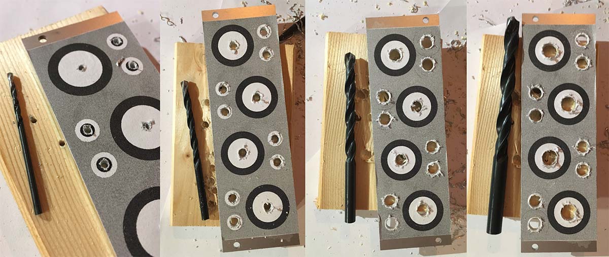
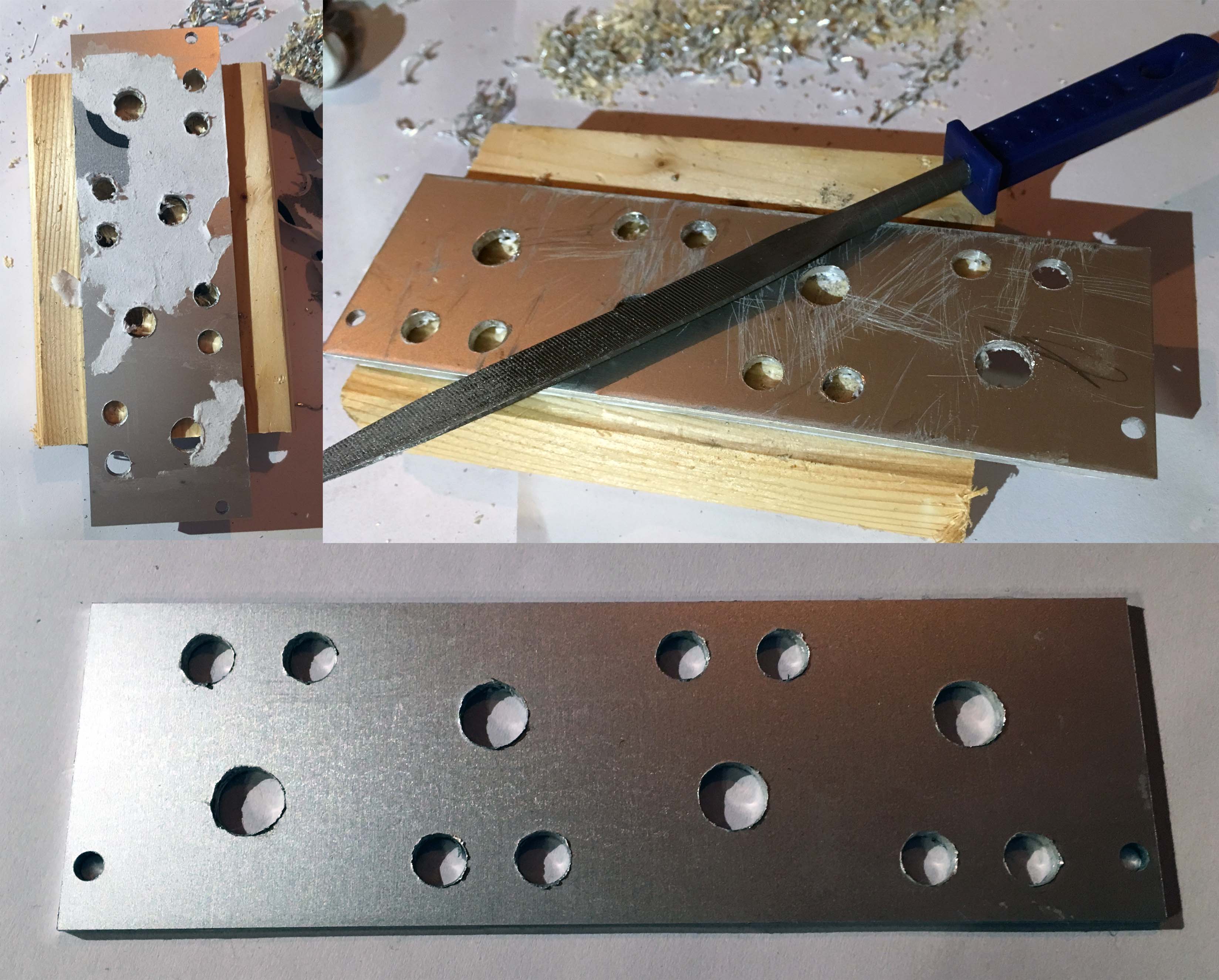
Drilling left the edges of the holes quite messy so I cleaned them up with a file. The glued design print was removed using acetone (cheap nail polish remover).
The shafts of the potentiometers were too long to fit the knobs close to the plate so they needed to be shortened with a metal saw.
Now it was time to place the components on the module plate. I needed to mount one of the potentiometers rotated by 180 degrees to leave enough space for the rack rails that would hold the module in place later.
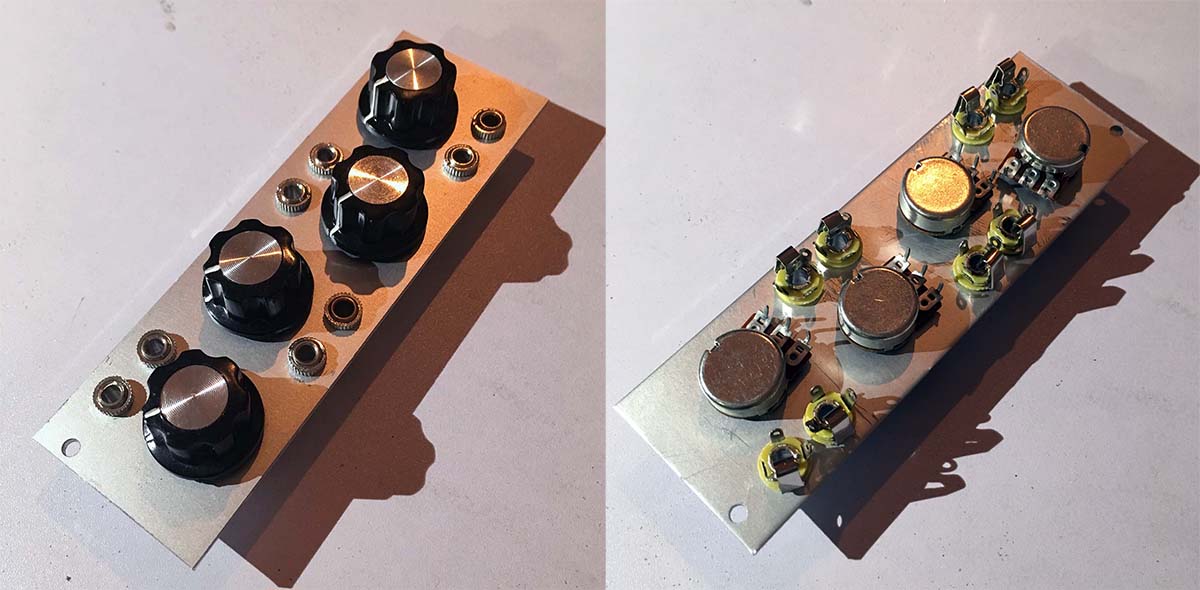
The TS jacks that I had bought turned out to be not so great, they were very stiff when plugging into and hard to solder. I ended up switching them out for different ones.
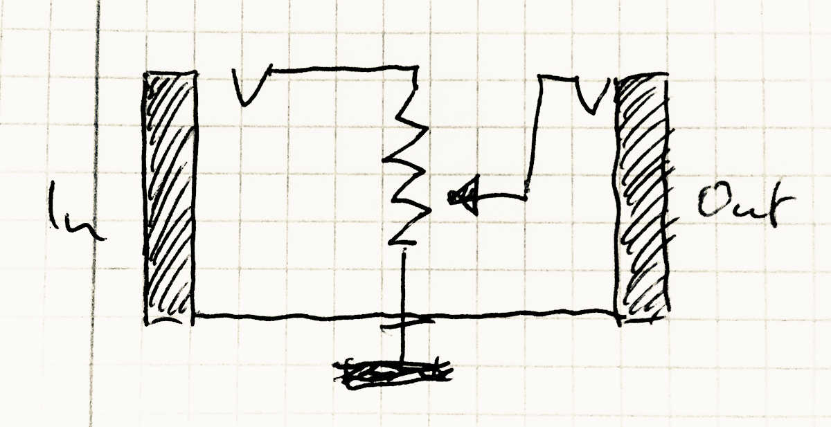
Now I could solder them to the potentiometers according to Doepfer’s schematic. The sleeve contacts of the input and output jack both went to pin 1 on the potentiometer, the tip of the output jack to pin 2 and the tip of the input jack to pin 3.
After testing everything with a multi-meter the module was ready to go into the rack.
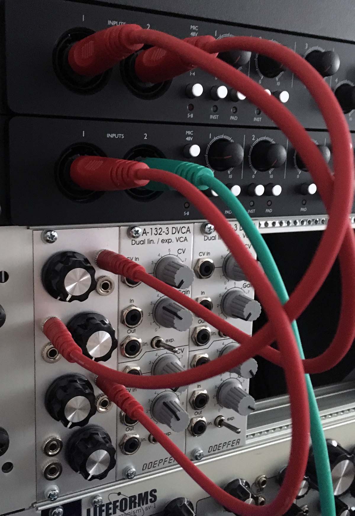
Everything turned out to work nicely and now I can use my VCAs for something else.
Not counting the bad jacks I got at first I spent about 20€ on materials. Building this module took about 6 hours total spread out over a weekend. With 8HP the module is also relatively small. After all, rack space is precious.